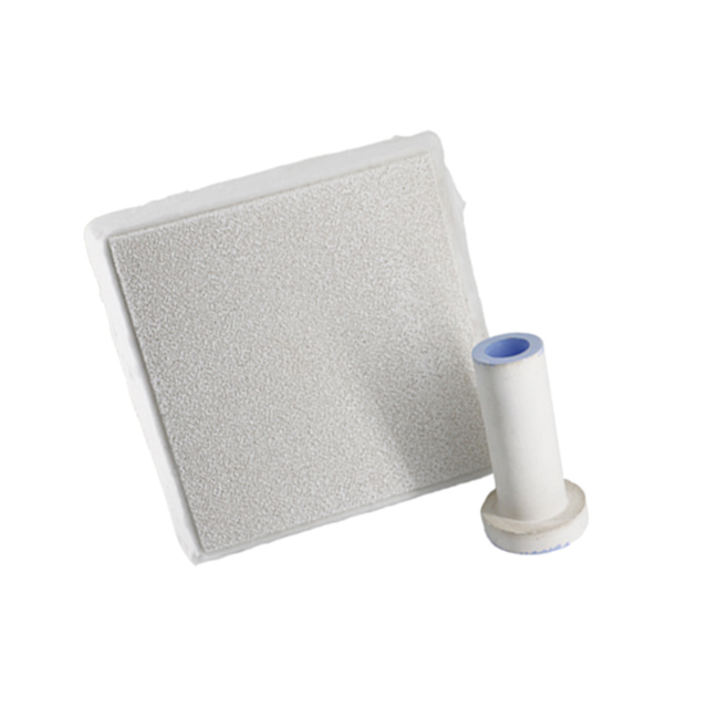
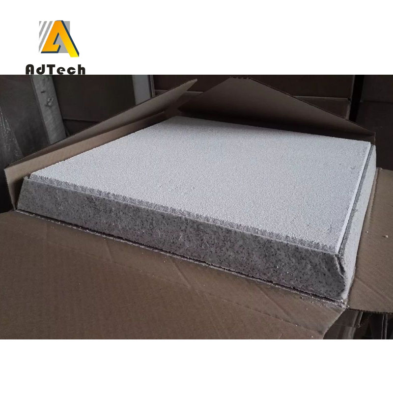
22 7月 Lanik Foam Ceramic Filter
Lanik Foam Ceramic Filter should be based on the quality requirements of the casting and the number of inclusions in the molten aluminium to determine the pore size of the filter. The size of the filter is determined based on the pouring speed and pouring weight.
When choosing Foam Ceramic Filter, we must consider the following aspects
Casting material/pouring temperature/pouring head height/pouring volume/pouring time
In order to ensure the filtering effect of the filter, the placement of the filter, the design of the gating system should also follow certain specifications.
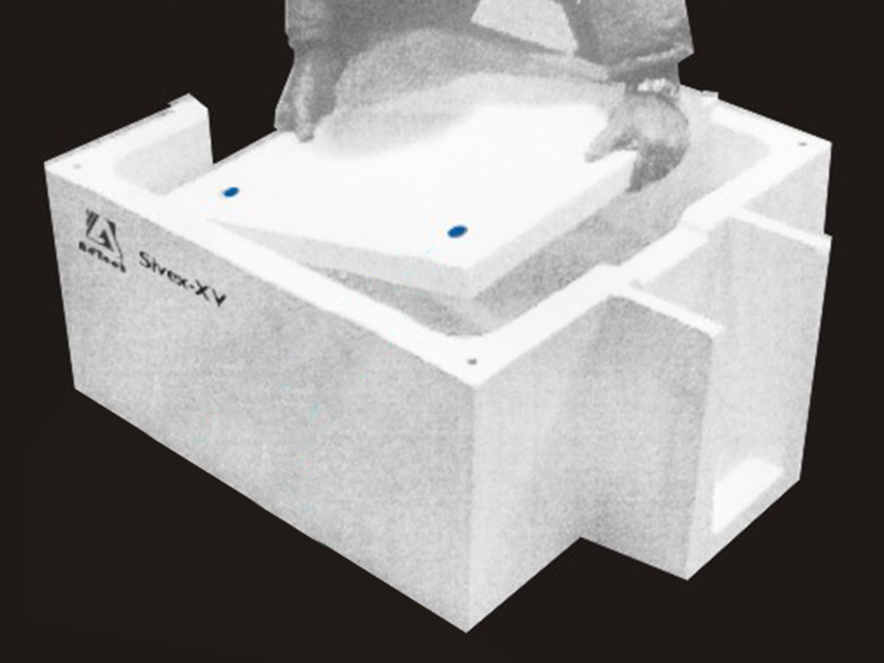
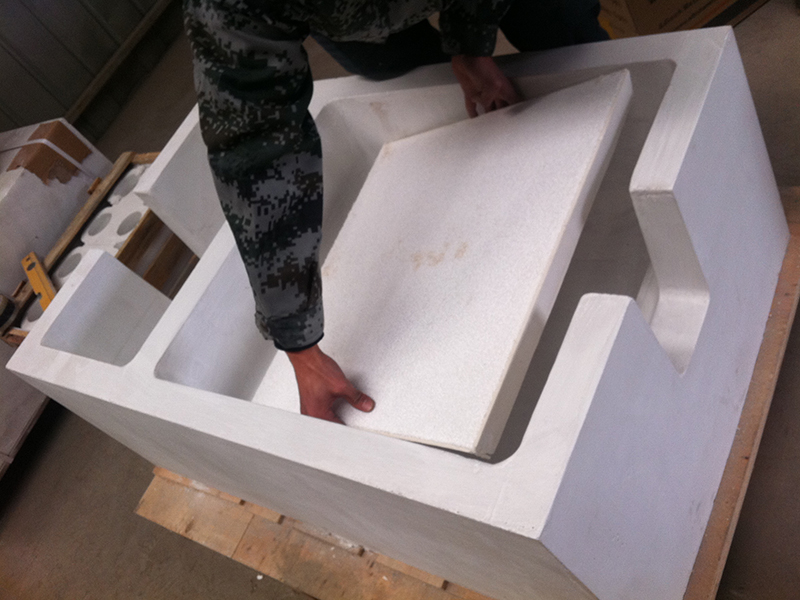
The installation of the filter The filter must be placed as close as possible to the casting to obtain the maximum filtration efficiency and flow adjustment.
Considering practical factors, such as the position that can be placed in the mold and the design of the gating system, the filter is often placed in the runner.
Sometimes the filter is placed at the bottom of the sprue, but this is not recommended.
Because the filtering effect and flow adjustment of the ceramic foam filter will be affected by the turbulence from the bottom of the sprue to the runner. It is recommended to install the filter vertically in the runner.

Overcurrent velocity of Lanik Foam Ceramic Filter
Most of the castings with filter flow rate have a critical pouring time, which corresponds to the best pouring speed.
Pouring speed is usually derived from experience or observation of a large number of castings in a particular foundry.
In some foundries, by setting the cross-sectional area ratio of each part of the gating system (cross-sectional area of sprue: sum of cross-sectional area of runner: sum of cross-sectional area of inner gate) to ensure proper flow rate.
Various filter media show a certain degree of pressure drop because they greatly adjust the flow of molten iron.
In order to reduce the influence of the filter on the velocity of molten iron, the flow area of the filter should be much larger than the flow control area of the gating system.
Metal overflow before the filter is blocked. All filters have a limit metal overflow before they are completely blocked.
Due to the filtering out of the inclusions, the effective flow area of the filter is reduced and flow obstruction occurs.
In extreme cases, exceeding this limit can cause the flow through the filter to stop completely.
The flow capacity of the filter varies greatly with the inclusion content in the molten iron, the pouring temperature and the design of the pouring system.
The foundry can determine how much flow area the filter needs based on the flow value and the pouring weight of the casting.


Sorry, the comment form is closed at this time.